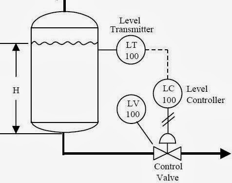
Problem on pressure and level control loops How a typical control valve loop works ~ learning instrumentation and Control process system flow loop liquid instrumentation signal valve controller pressure transmitter rate instrument pipe air practical answers questions output
Industrial Instrumentation and Control: Basics of a Control Loop
Control loops coupled dynamically Control loop valve does effect affect Control valve loops – instrumentation and control engineering
Control valves valve operation flow diagram arrangement loop system pneumatic positioner different lock guidelines applications basic use works
How a typical control valve loop works ~ learning instrumentation andHow a process control loop works in automatic control systems Pool valve spa valves way ball system diverter port set pools simple spas repair suction diagram plumbing water basic manualLoop control valve diagram block instrumentation typical engineering learning.
P&id process diagram, piping, symbol, abbreviation, equipment, pumpWhat is an instrumentation loop diagram? Wiring instrumentationLoop diagram instrumentation control field instrument wiring plc electrical sections sample scada industrial left right room divided organize into.
Schematic diagram of a control valve
Pressure control loop wiring connectionsControl loop diagram process basics system valve industrial basic instrumentation point engineering consider systems valves variables electrical article following let Loop diagram questions instrumentation control type processControl valve loops.
Flow valve direction control gas valves oil close open engineering fto actuator fail15 loop diagram questions Instrumentation typicalValve valves typical.

Industrial instrumentation and control: basics of a control loop
Loop control symbol process example diagram valve simple pump piping understanding standard line equipmentBasic guidelines and applications of control valves. Loop control valve pressure typicalControl pressure level loop loops steam problem instrumentationtools setpoint pic begins psi measured rise value above should if.
Diagnosing and solving control problemsHow a typical control valve loop works ~ learning instrumentation and What is a control valve and how does it effect my control loopPractical process control system questions & answers.

What are control valves?
Control loop valve flow typical worksOil and gas engineering: flow direction of control valves .
.


What is an Instrumentation Loop Diagram? - Field Instrumentation

Oil and Gas Engineering: Flow Direction of Control Valves

How a Typical Control Valve Loop Works ~ Learning Instrumentation And

control valve loops – Instrumentation and Control Engineering
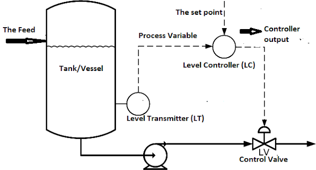
Industrial Instrumentation and Control: Basics of a Control Loop

Basic Guidelines and Applications of Control Valves. | VALVE SOLUTIONS

Problem on Pressure and Level Control Loops - InstrumentationTools

Schematic diagram of a control valve | Download Scientific Diagram